

The first prototype. Size was less of a problem then anticipated. The breadboard and bluetooth module fit snugly but the Ultrasonic sensor and the Arduino do not fit nearly as well. The ultrasonic sensor requires holes for the speakers/receivers, these holes are too far apart. The Arduino requires holes for the data and the power ports so it can fit snugly.


The second version of the housing is better in many aspects. the breadboard slot is wide enough that the breadboard won't get stuck. The bluetooth slot is the right depth so the module will not sink deeper and deeper making it impossible to get out. As depicted in the second photo, the holes for the ultrasound sensor are the right size. However, the box is too small for the device to fit. The holes for the Arduino are too far apart as well. This new version is better in many aspects and shows many ways for which I will have to solve new problems.


The new casing and the frame that represents the dimensions for the lid. The new casing holds everything perfectly. The holes for the Arduino work very well as do the holes for the ultrasound sensor. The holes for nuts and bolts(can be seen in the previous picture) are much too big to the point where the nut heads were falling into the hole. I added the washers to see how the ensemble would hold together.

The cylinder above is the first size test for the cylinder which will allow the casing to slide. The size was found to be big by 4 mm.

The green part is the second size test for the sliding portion of the casing. After subtracting four millimeters from the diameter of the previous iteration. It now fits like a glove and the dimensions will be used in the casing itself.


A new print of the shuttle came to fruition after seven hours of printing. The print had a small bug in it, with a skew in the top third of the print(see first image.) Since there was only one place where the print was shifted, I was able to saw off the part and hot glue it back into the right place (see images two and three.) However, there holes for the shafts were not well aligned. I resolved this by filing down the edges into a much smoother shape, without any significant edges on the inside where it had been glued(see final image.)


The latest print of the shuttle, with the correct size for the rods implemented. A bottom has also been added so that the parts do not fall through. However, I did find that the cylinders were not connected well enough.

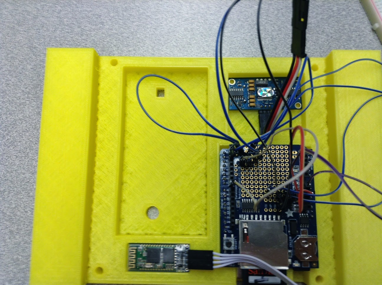
The new print of the housing has arrived. The part which will hold the the shaft has changed into a square holder, which will be more sturdy then the previous circular ones. The breadboard has also been removed and been replaced with a shield and a space for the laser range finder.

The first iteration of the part which will hold the rods as well as the rubber tread. The design is drastically flawed because the two halves, when put together, are not lined up at all. Changes have been made but have yet to be printed. The holes are the correct size to hold the rods but are too far apart.

A new iteration of the housing had to be designed due to the shape of the laser range finder. The way the pins were placed and it's inability to have a strong hold on the housing itself, a small bar was added to hold it in place. This will allow for greater accuracy.


The prototype is ready! It is capable of moving in both directions and can sense distance accurately. It doesn't move very quickly because the stepper uses a lot of memory. The prototype accurately demonstrates the concept I am attempting to prove.
No comments:
Post a Comment